

close
Choose Your Site
Global
Social Media
Views: 0 Author: Site Editor Publish Time: 2026-10-24 Origin: Site


Engineers, facility managers, and procurement specialists face a constant daily battle against equipment wear. Choosing the wrong power transmission unit often leads to excessive downtime. It triggers strict noise compliance issues and causes premature mechanical failure. When production lines stop, the impact stretches across the entire operation. You need a highly robust solution to keep systems running smoothly.
Enter the standard Helical Gear Motor. It serves as the undisputed baseline in high-torque, continuous-duty applications across heavy industries. Many plants rely on it to handle immense forces day after day. This article moves beyond a basic mechanical explanation. We frame this guide as a detailed buyer’s framework. You will learn how to evaluate if this specialized gearing technology is the right technical fit for your specific operational demands. We will guide you through mechanics, trade-offs, and critical specification steps.
Progressive Engagement: Helical gears utilize angled teeth for gradual contact, delivering smoother, quieter, and higher-load power transmission than spur gears.
The Trade-off (Axial Thrust): The angled design creates axial (thrust) forces, requiring specialized thrust bearings and precise lubrication strategies.
Primary Applications: Ideal for high-speed, high-torque environments like automotive transmissions, heavy-duty conveyors, and extruders.
Evaluation Criteria: Selection must be driven by service factor requirements, spatial constraints, and noise compliance standards.
Many traditional drive systems rely on spur gears. Spur gears feature straight teeth oriented parallel to the gear shaft. These straight teeth engage all at once. This sudden contact creates severe impact loading. It generates intense vibration and produces high decibel levels. Facility managers often struggle to maintain noise compliance when operating large spur gear setups.
The solution lies in modifying the gear geometry. A Helical Gear Motor introduces a critical design change. Engineers cut the gear teeth at a specific angle to the gear axis. We call this the helix angle. This angled design allows for progressive tooth engagement. Instead of slamming together, the teeth slide into contact gradually. The engagement begins at one end of the tooth. It sweeps smoothly across the face as the gear rotates. This overlapping action ensures multiple teeth share the mechanical load at any given moment.
This design dramatically transforms power transmission flow. The motor shaft generates high-speed kinetic energy. It transfers this rotational force into the helical gear set. The gear mesh absorbs this energy smoothly. It multiplies the output torque while proportionally reducing the revolutions per minute (RPM). The resulting power delivery is exceptionally stable.
However, we must conduct a realistic efficiency check. These systems deliver high efficiency ratings. They routinely achieve 95% to 98% efficiency per gear stage. But the physical mechanics introduce a catch. The progressive sliding action creates inherent sliding friction. This friction generates substantial heat during continuous operation. Heat generation directly impacts the thermal rating of the unit. Operators must account for thermal limits to prevent unexpected breakdowns.
Selecting the right drive unit requires objective analysis. You must balance the clear operational benefits against the necessary engineering concessions.
The angled tooth geometry unlocks several major operational advantages. First, it maximizes load capacity. Because multiple teeth share the load simultaneously, stress distributes evenly. This load sharing allows for significantly higher torque transmission. You achieve this power within a highly compact physical footprint. Plant engineers value this spatial efficiency greatly.
Next, we must consider noise reduction. Progressive engagement significantly lowers decibel output. Straight-cut gears whine loudly under heavy loads. Helical gears operate with a smooth, muted hum. This reduction proves crucial for plants enforcing strict OSHA noise limits. Local noise compliance standards increasingly dictate equipment selection. A quieter motor protects worker hearing and prevents regulatory fines.
Finally, the design promotes exceptional longevity. Smoother tooth engagement reduces dynamic loading. It minimizes the harsh shocks transmitted through the gear teeth. Less shock means less metal fatigue. This translates directly to reduced wear and a longer operational lifespan.
Every mechanical advantage requires a trade-off. We must transparently address the primary drawback of this technology. The helix angle introduces axial thrust forces. As the angled teeth push against each other, they generate a side-loading force. This force attempts to push the gears apart axially along the shaft.
Overcoming this thrust requires robust bearing requirements. Standard ball bearings cannot handle intense side loads. Engineers must integrate heavy-duty thrust bearings or tapered roller bearings into the housing. These specialized bearings absorb the axial forces effectively. However, they add significant weight, complexity, and initial cost to the motor.
Additionally, these systems exhibit strict lubrication dependency. The sliding friction between gear teeth demands specific fluid protection. Standard machine oils will fail quickly. You must utilize high-viscosity gear oils. These lubricants contain extreme pressure (EP) additives. They prevent metal-to-metal scoring and manage the heat generated by the sliding action.
Table 1: Drive System Mechanical Comparison Chart
Feature | Spur Gear Systems | Helical Gear Systems |
|---|---|---|
Tooth Engagement | Sudden, full-face contact | Gradual, sliding contact |
Noise Level | High (Whining/Clanking) | Low (Smooth humming) |
Load Distribution | Single tooth bears full load | Multiple teeth share load |
Axial Thrust Force | Minimal to None | High (Requires thrust bearings) |
Manufacturing Cost | Lower | Higher |
Specific industries mandate this technology based on concrete business outcomes. Why do major sectors refuse to use alternative gear types? The answers lie in operational demands.
Automotive & Mobile Machinery: Automotive transmissions rely entirely on helical gears. Drivers demand reliable power transfer at wildly varying speeds. They also demand quiet cabins. Straight-cut gears would produce unbearable cabin noise. The progressive mesh delivers low-noise power transfer effortlessly.
Material Handling & Conveyors: Mining operations and distribution centers run massive conveyors. These belts handle continuous, heavy shock loads. Sudden weight shifts destroy weaker gears. A Helical Gear Motor absorbs these shock loads smoothly. It prevents catastrophic structural fatigue across the drive train.
Extruders & Mixers: Chemical plants and plastic manufacturers operate massive extruders. These machines require constant, high-torque rotation pushing through thick materials. If an extruder jams, production stops. Downtime in these sectors costs thousands of dollars per hour. The inherent load capacity of angled gears ensures uninterrupted extrusion.
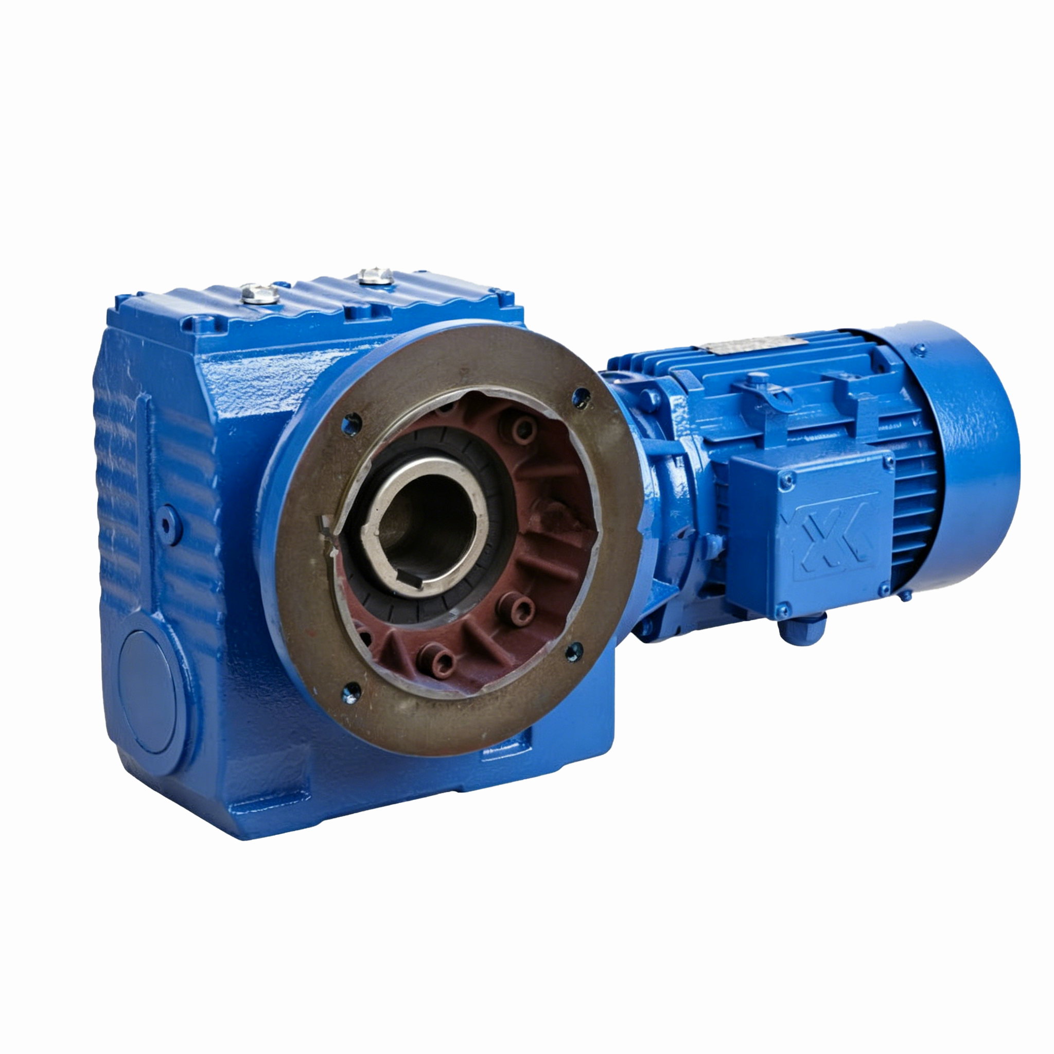
Purchasing top-tier equipment does not guarantee success. Improper installation and poor maintenance will destroy even the best gearboxes. You must manage several critical implementation realities.
Alignment criticality remains the primary installation risk. Technicians must align the motor shaft and the driven load perfectly. Misalignment during installation creates chaotic stress patterns. It amplifies the existing axial thrust forces unpredictably. Unmanaged thrust leads directly to rapid bearing failure. It can destroy a brand-new bearing assembly within weeks. Always use laser alignment tools during commissioning.
Thermal management dictates long-term survival. The sliding friction produces continuous heat. You must monitor operating temperatures rigorously. This proves especially vital in continuous-duty applications. High ambient heat in summer months compounds the problem. If the gear oil exceeds its thermal limit, it degrades rapidly. It loses viscosity and stops protecting the metal. Use infrared thermography during routine inspections to catch heat spikes early.
Strict lubrication protocols are non-negotiable. You must set realistic expectations for maintenance intervals. Ignoring oil changes in these specific systems is disastrous. It leads to accelerated wear much faster than in less friction-heavy designs. Follow a rigid protocol:
Initial Break-in Drain: Drain and replace the factory oil after the first 500 hours of operation to remove manufacturing particulates.
Routine Sampling: Pull oil samples every six months. Analyze them for microscopic metal flakes.
Scheduled Replacement: Replace synthetic gear oil every 5,000 to 10,000 operating hours, depending on ambient dust and heat levels.
Viscosity Verification: Ensure technicians only refill using the exact high-viscosity, extreme-pressure (EP) lubricant specified by the manufacturer.
Do not guess when sizing a drive unit. Engineers must define clear success criteria. Instruct your internal team to map all requirements thoroughly before engaging vendors. A vague request leads to underperforming equipment.
You must evaluate several key sourcing dimensions. First, calculate your exact Torque and RPM requirements. Determine both the continuous running load and the peak starting load. The motor must handle the absolute highest spike in torque without stalling.
Next, evaluate the Service Factor (SF). The service factor acts as your safety margin. It accounts for the application's shock load and duty cycle. Industry standards set by organizations like AGMA dictate these calculations. For a smooth, 8-hour daily run, a 1.0 SF might suffice. However, for a rock crusher running 24/7, you must specify a 1.5+ SF. This ensures the unit survives heavy shock without shearing teeth.
Finally, consider your mounting and footprint constraints. Analyze the available spatial envelope on your factory floor. Do you need an inline configuration where the motor and output shaft sit on the same axis? Or do you need a parallel shaft configuration to fit into a tighter horizontal space?
Your next-step action is clear. Advise your team to prepare a comprehensive spec sheet. Document the ambient operating conditions, duty cycles, and spatial limits. Present this standardized document to multiple vendors. This ensures all vendor quotes are accurate, competitive, and truly comparable.
A well-specified Helical Gear Motor represents a strategic investment in facility reliability. It guarantees operational quietness and smooth power delivery, provided you engineer properly for the axial thrust. By understanding the mechanical realities, you avoid common installation pitfalls and maintenance failures.
The final verdict remains clear. This technology is best suited for high-torque, continuous operations. The upfront cost of specialized thrust bearings and synthetic lubricants is easily justified by immense long-term durability. It keeps critical production lines moving without unexpected interruptions.
Do not leave your next drivetrain selection to chance. Contact our engineering team today for a comprehensive application review. You can also download our complete sizing and specification guide to ensure your next installation meets every operational demand perfectly.
A: They are highly efficient systems. They typically achieve 95% to 98% efficiency per gear stage. However, maintaining this efficiency depends entirely on proper lubrication and operating within the designed load parameters. Overloading the motor or using degraded oil increases sliding friction, which lowers overall efficiency and generates excessive heat.
A: Yes, they can operate effectively in reverse. The gear teeth mesh identically in both rotational directions. However, running in reverse changes the direction of the axial thrust forces. Ensure the internal thrust bearings are specifically configured to handle bidirectional axial loads before reversing the motor frequently.
A: Helical drives offer significantly higher efficiency and run much cooler under heavy continuous loads. They transfer more motor power directly to the application. Worm gears generate far more friction and heat. However, worm gears offer extreme right-angle compactness and unique self-locking features, preventing back-driving in lifting applications.