High-torque applications expose power transmission systems to severe shock loads and continuous strain. Mixing highly viscous fluids or crushing heavy aggregates creates extreme mechanical stress. A standard gearbox will usually fail prematurely in these harsh industrial environments. Such failures lead to unacceptable production downtime and massive maintenance burdens. Specifying the correct heavy duty helical gearbox requires moving far beyond nominal horsepower calculations. It demands a rigorous evaluation of service factors, thermal ratings, and precise mounting geometries. You must accommodate highly specific radial and axial forces to ensure long-term reliability.
This guide provides a comprehensive specification framework for engineering teams. We will show you how to evaluate, size, and perfectly integrate heavy-duty gear systems. You will learn to match mechanical capabilities to your exact application. You can achieve this without over-engineering or under-specifying your final drive solution.
Key Takeaways
Torque over Horsepower: Sizing must prioritize output torque and operational service factors over standard motor horsepower to account for the severe shock loads typical of crushers and heavy mixers.
Mounting Dictates Longevity: Selecting the correct mounting configuration (foot, flange, or shaft-mounted) is critical for managing overhung loads and ensuring shaft alignment.
Thermal vs. Mechanical Ratings: A high power helical gearbox may possess the mechanical strength for an application but fail due to exceeding thermal limits; both must be evaluated independently.
TCO and Serviceability: Upfront specification must include considerations for lubrication paths, condition monitoring, and ease of maintenance in harsh environments.
The Business Case for Specificity: Why Mixers and Crushers Demand Purpose-Built Drives
You must understand the exact stresses these applications inflict on machinery. Crushers process raw aggregates and ores. These materials do not yield easily. They generate high-impact, irregular shock loads during operation. Mixers introduce varying viscosity friction as chemical or food products blend. As fluids thicken, rotational resistance increases drastically. This creates massive axial loads pressing directly on the main agitator shaft.
You cannot ignore the staggering cost of equipment failure. Premature bearing failure halts production immediately. Severe shock events cause complete gear tooth shear. Unplanned maintenance in continuous-process industries costs thousands of dollars per hour. You lose revenue while maintenance teams struggle to replace shattered internal components.
Standard commercial gearboxes will consistently fail here. They lack the structural rigidity required for high-stress environments. A dedicated crusher gear drive or an application-specific mixer gearbox utilizes completely different internal architectures. They require heavily hardened steel gearing to resist sudden impacts. Housings feature reinforced cast iron or fabricated steel walls. Manufacturers utilize precision-ground helical profiles. These optimized profiles guarantee maximum contact ratio between mating gears. A high contact ratio distributes physical stress evenly and prevents localized tooth fracture under load.
Sizing the Industrial Helical Gear Reducer: Torque Ratings and Service Factors
Engineers often confuse nominal torque and required application torque. Nominal torque assumes ideal, uniform running conditions inside a laboratory. Required application torque reflects real-world operational stress. You calculate standard output torque by integrating motor speed, reduction ratio, and mechanical efficiency. But calculating base torque is merely your starting point. An industrial helical gear reducer must survive peak operating forces far beyond its baseline rating.
We use established AGMA and ISO service factors to protect equipment. These factors act as essential safety multipliers against premature failure. You must evaluate several operational modifiers. Consider the total hours of operation per day. Analyze the load profile carefully. Mixers usually present uniform or moderate shock loads. Crushers generate exceptionally heavy shock loads. A rock crusher running continuously requires a much higher service factor.
However, you must avoid the trap of excessive over-sizing. Some engineers arbitrarily double the required service factor. This practice unnecessarily increases upfront equipment costs. It demands a significantly larger installation footprint. Massive gearboxes paired with standard motors reduce optimal electrical efficiency. You should always match the service factor precisely to published application load classifications.
Mixers and crushers apply severe external forces to their driven shafts. Chain or belt drives on crushers pull laterally. This action creates severe radial loads, widely known as overhung loads. Large impellers on vertical mixers push up or down continuously. This movement creates massive axial thrust loads. You must evaluate these specific directional forces. Compare your calculated values against the manufacturer's permissible load charts. If your application exceeds these baseline limits, you must specify upgraded output bearing packages.
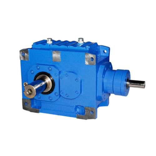
Mounting Configurations: Integrating the Heavy Duty Gear Unit
Foot mounting remains the industry standard for horizontal power transmission. You typically see them on rigid baseplate assemblies coupled directly to crushers. They offer exceptional foundational support for massive drive packages. But implementation realities often complicate the installation process. You must achieve precise laser alignment between the motor, gearbox, and driven load. Poor alignment destroys flexible couplings rapidly. It also transfers destructive vibration frequencies directly into the heavy duty gear unit.
Flange mounting serves perfectly for vertical mixing applications. The gearbox bolts directly onto the upper mixer support structure. You must ensure this support structure possesses exceptional rigidity. Any flexing will distort the gearbox housing during heavy mixing cycles. Furthermore, vertical orientations demand specialized dry-well construction. A dry-well design incorporates extended internal dams. These dams prevent fluid from pooling near the lower output shaft bearing. This critical feature stops lubrication from leaking down the agitator shaft into your valuable product.
Hollow shaft designs deliver massive space-saving benefits for crowded facilities. They slide directly onto the driven machine shaft. This eliminates the need for massive concrete base foundations. You also completely remove external couplings from the drive assembly. However, you must mitigate a specific operational risk. Shaft-mounted drives require correctly engineered torque arms. The torque arm absorbs all rotational reaction forces. If you design the torque arm incorrectly, it restricts natural shaft movement. This restriction causes severe housing distortion and immediate bearing failure.
Comparing Gear Architectures: Helical vs. Bevel-Helical and Planetary Options
Parallel shaft helical designs offer continuous, high-efficiency power transmission. They perform best in operations where the facility allows a longer installation footprint. They generate very low internal heat due to minimal sliding friction. They also provide exceptional long-term reliability. We highly recommend them for standard bulk material handling.
Many industrial sites suffer from severe space constraints. Right-angle configurations solve these installation footprint problems effectively. They utilize a bevel gear set on the primary input stage. You will notice a slight mechanical efficiency drop compared to parallel helical units. The perpendicular power transfer creates marginally more friction. However, they remain highly suitable for heavy conveyor belts and primary crusher feeds.
Engineers often compare helical boxes against planetary or worm gear alternatives. Planetary units deliver much higher torque density in a significantly smaller package. But they feature highly complex internal carrier arrangements. This complexity makes field maintenance very difficult for standard plant technicians. Worm gears present a completely different problem. They suffer from high sliding friction across the gear teeth. This makes them highly inefficient for high continuous torque requirements in heavy-duty applications.
Gear Architecture
Best Application
Efficiency
Maintenance Complexity
Standard Helical (Parallel)
Mixers, large pumps, continuous high-load operations
Implementation Realities: Lubrication, Thermal Capacities, and Compliance
Engineers often misunderstand the physical limits of a high power helical gearbox. These robust units usually reach their thermal limit long before their mechanical limit. The internal steel components possess massive structural integrity. They handle heavy torque easily. However, the cast housing cannot radiate friction heat fast enough to cool the oil. You must specify dedicated cooling solutions. Common methods include auxiliary cooling fans mounted directly to the high-speed input shaft. Large industrial systems often require external water-to-oil heat exchangers. Switching to premium synthetic lubrication also dramatically reduces internal operating temperatures.
Standard splash lubrication works perfectly for many horizontal applications. The lower gears dip into an oil bath and throw fluid onto the upper bearings. But heavy shock loads often require forced lubrication systems. A dedicated mechanical pump actively sprays oil directly into the gear mesh. Cold-start conditions dictate specific lubrication heating packages. Thick, viscous oil will not flow properly in freezing environments. Extreme operating angles also alter the internal static oil level. You must modify standard splash guards to accommodate steep installation angles.
Equipment compliance ensures operational safety and longevity. You must specify units conforming to strict AGMA (American Gear Manufacturers Association) or ISO standards. These organizations define precise gearing geometries for the entire industry. They also mandate specific material core hardness levels. Relying on recognized engineering standards prevents catastrophic structural failures during peak production runs.
Shortlisting Your High Power Helical Gearbox: A Specification Framework
Procurement teams must collect precise operational data before requesting vendor proposals. Incomplete data always leads to incorrect physical sizing. You must include these non-negotiable details in your Request for Quote (RFQ):
Precise input horsepower and base motor RPM.
Exact required reduction ratio for the driven machine.
Daily duty cycle and expected hourly starting frequency.
Ambient temperature range of the operational facility.
Strict dimensional constraints for the final installation footprint.
You must assess potential manufacturing vendors carefully. Use a structured evaluation process:
Look for companies providing fully transparent engineering data alongside their quotes.
Demand to see their complete thermal and mechanical rating calculations.
Check for the ready availability of customized output shafts or specialty flanges.
Review the warranty terms specifically designed for heavy-shock applications.
Move beyond preliminary sizing calculations as quickly as possible. Engage directly with vendor application engineers. Request full 3D model integration files for your assembly layout. Perform a final dynamic load verification check. Ensure your calculated overhung loads perfectly match the selected bearing life capabilities.
Conclusion
Specifying a heavy-duty power transmission system involves highly complex engineering decisions. You are constantly balancing maximum mechanical strength against absolute thermal limits. You must also integrate the drive unit into strict physical geometries. A superficial look at base motor horsepower will guarantee early equipment failure in a crusher or mixer.
We strongly advise prioritizing transparent load data from your vendor. Apply realistic service factors based strictly on accurate application profiles. Do not prioritize the lowest initial purchase price over guaranteed long-term reliability. A cheap drive unit costs exponentially more when it unexpectedly halts your entire production line.
Take proactive action before finalizing your next procurement cycle. Download a technical specification checklist. Request an intensive engineering consultation from a trusted manufacturer. Submit your detailed application data for a custom, comprehensive torque analysis today.
FAQ
Q: How do I determine the correct service factor for a rock crusher gear drive?
A: Base your calculation on AGMA guidelines for heavy shock and continuous operation. Rock crushers typically require a service factor between 1.75 and 2.0 or higher. The exact multiplier depends on specific aggregate density and continuous feed rates. Always consult the manufacturer's load classification tables for precise validation.
Q: Why is thermal rating often lower than mechanical rating in a high power helical gearbox?
A: Mechanical rating measures structural integrity, specifically gear tooth strength. Thermal rating indicates the ability of the housing to dissipate internal heat. In continuous high-speed operations, mechanical friction generates heat much faster than the housing radiates it. This imbalance necessitates auxiliary cooling to prevent oil breakdown.
Q: Can a standard parallel shaft gearbox be mounted vertically for a mixer?
A: You cannot mount it vertically without significant internal modification. Vertical mounting requires specific internal lubrication adaptations. You need internal oil pumps or modified splash guards. You also need specialized dry-well seals to prevent fluid leaks and ensure upper bearings never run dry.
Q: What is the advantage of a hollow shaft design in heavy duty gear units?
A: A hollow shaft design eliminates the need for rigid couplings and separate concrete base foundations. This vastly reduces the installation footprint and prevents major shaft alignment issues. However, you must correctly specify the torque arm to handle all operational reaction forces safely.