In industrial process automation, the reliability of a control loop depends entirely on its final control element. Precision fluid handling requires exact mechanical execution of digital or analog commands. A programmable logic controller can calculate the exact flow rate required, but if the valve cannot physically reach that specific position, the process degrades. Specifying the wrong actuator configuration leads to premature motor failure, inaccurate flow control, integration bottlenecks with existing networks, and unplanned downtime.
Moving beyond basic definitions, this guide provides a technical evaluation framework for Electric Actuator Controls. We detail how to align motion types, power availability, control signals, and environmental ratings with specific process requirements. By understanding the mechanical and electrical nuances of these devices, you can ensure proper integration, eliminate control hunting, and maximize the operational lifespan of your fluid handling systems.
Motion dictates selection: Matching the actuator's mechanical output (multi-turn, part-turn, or linear) to the specific valve stem design is the non-negotiable first step in specification.
Control precision varies: Applications require distinct control logic, ranging from basic discrete (on/off) operation to continuous, pinpoint positioning using a modulating electric actuator and dedicated positioner.
Sizing requires safety margins: Accurate torque and thrust calculations must account for breakaway friction, dynamic fluid forces, and appropriate safety factors to prevent motor stalling.
Power and environment dictate lifespan: Matching available site voltage, enclosure ratings, hazardous area certifications, and duty cycle limits is critical to preventing catastrophic failure in harsh operating conditions.
Understanding Electric Actuator Controls in Process Automation
Transitioning from manual operation or legacy pneumatic systems to an automated electric setup requires clear engineering goals. Facilities make this transition to achieve improved positioning accuracy, eliminate the maintenance burden of compressed air infrastructure, and gain access to enhanced diagnostic data. A well-specified electric system provides repeatable, high-resolution control essential for complex process loops. You must define what success looks like for your specific application before selecting hardware.
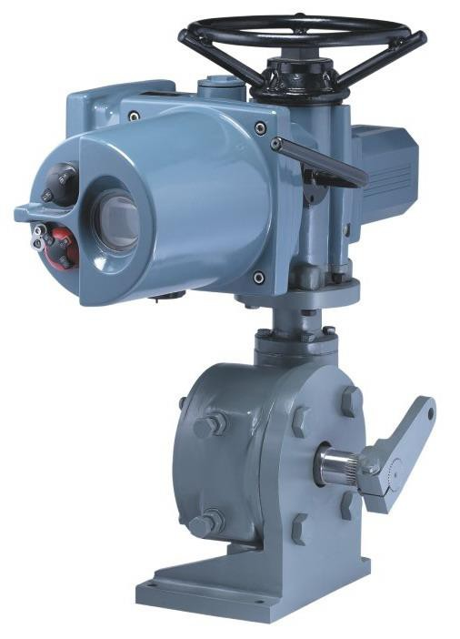
The fundamental architecture of these devices relies on several interconnected core components. The electric motor and gear train multiply torque or thrust, converting high-speed motor rotation into powerful mechanical force. The logic board translates incoming electronic signals into precise motor movements. Limit and torque switches provide end-of-travel protection, ensuring the motor stops before damaging the valve trim. A manual override handwheel allows for commissioning, mechanical calibration, and emergency operation during power outages.
Engineers must look objectively at performance characteristics when comparing electric and pneumatic systems. Electric controls offer superior precision and eliminate the risk of freezing air lines in cold environments. They typically feature slower stroke speeds compared to the rapid actuation of pneumatic cylinders. Pneumatic systems offer fast-acting performance but require continuous maintenance of the plant air supply to prevent moisture and debris from degrading internal seals.
Performance Metric
Electric Actuation
Pneumatic Actuation
Power Source
Site electrical grid (24VDC, 120VAC, 480VAC)
Plant compressed air system (typically 80-120 psi)
Stroke Speed
Slower, highly controlled, adjustable via VFD
Very fast, difficult to precisely control mid-stroke
High (filter replacement, air line draining, seal checks)
Cold Weather Operation
Excellent (internal space heaters prevent condensation)
Poor (moisture in air lines freezes and blocks ports)
Evaluating Actuator Motion Types for Specific Valve Designs
Categorizing actuators by their mechanical output is the foundation of specification. The motion generated by the motor and gearbox must perfectly match the valve trim and required travel distance. Forcing an incompatible motion type onto a valve body results in immediate mechanical failure or severe operational limitations.
Multi-Turn Valve Actuator Applications
These units are mechanically capable of multiple 360-degree rotations. This rotation is necessary to move the valve trim from a fully open to a fully closed position over a long stroke. You will typically pair a multi-turn valve actuator with gate valves, globe valves, and certain types of pinch valves. When evaluating these applications, engineers must assess stem nut compatibility. Rising stem valves require a hollow output shaft in the actuator to allow the threaded stem to pass through as the valve opens. Non-rising stems require a different drive nut configuration. Additionally, these units must manage the high-torque seating requirements necessary to wedge a gate valve tightly into its seats without shearing the stem.
Part-Turn Valve Actuator Applications
Designed for fractional rotation, these devices typically operate within a strict 90-degree parameter. A part-turn valve actuator is the standard choice for ball valves, butterfly valves, and plug valves. The evaluation lens here involves managing the torque curve. Quarter-turn valves exhibit a non-linear torque requirement. The highest force, known as breakaway torque, is required to unseat the valve against maximum differential pressure. The torque requirement drops during mid-travel before spiking again as the valve closes against the hydrodynamic forces of the fluid. You must size the motor to handle the peak breakaway torque, not just the running torque.
Linear Valve Actuator Applications
Instead of rotation, these units provide direct push or pull linear motion. A linear valve actuator is compatible with diaphragm valves, pinch valves, and sliding-stem linear control valves. Specifying these units requires calculating the exact required stem thrust to overcome process pressure, fluid velocity, and packing friction. You must evaluate the coupling mechanisms to ensure they accurately and rigidly locate the valve plug. Any mechanical slop or backlash introduced into the control loop at the coupling point will cause erratic flow control and force the positioner to constantly hunt for the correct setpoint.
Control Signals and Positioning: On/Off vs. Modulating
Aligning the electronic control capabilities with the demands of the process loop is mandatory for operational stability. The logic board must interpret the signals sent by the distributed control system (DCS) or programmable logic controller (PLC) and translate them into appropriate physical movement.
Discrete Control (Open/Close)
Discrete control is utilized for isolation, emergency shutdown sequences, and basic batching operations where the valve only needs to exist in two states: fully open or fully closed. The control logic relies on simple relay-based commands. Limit switch feedback confirms the end-of-travel position back to the PLC. Torque seating protection ensures the motor shuts off if an obstruction prevents the valve from closing completely, thereby protecting the mechanical linkages from shearing under the motor's full stall torque.
Specifying a Modulating Electric Actuator
For applications requiring continuous flow, temperature, or pressure regulation, discrete control is insufficient. These scenarios require a modulating electric actuator. The control logic involves accepting analog signals, typically 4-20mA or 0-10V, via an integrated positioner. This allows the system to locate the valve proportionally based on the varying control signal. When evaluating modulating units, you must assess resolution and deadband adjustments. If the deadband is set too tight, the actuator will constantly hunt for the perfect position, leading to rapid motor burnout. If it is too wide, process control becomes sluggish and inaccurate. Proper PID loop integration capabilities are essential to maintain stability.
Digital Communication and Smart Actuators
Modern process facilities increasingly rely on smart actuators integrated with industrial networks. This digital integration provides immense value beyond simple positioning. Operators gain access to predictive maintenance data, allowing them to monitor torque profiles over time to detect valve wear before failure occurs.
HART Protocol: Allows digital diagnostic information to ride on top of standard 4-20mA analog wiring, making it ideal for retrofitting older plants.
Foundation Fieldbus: Enables distributed control directly in the field devices, reducing the processing load on the central DCS.
Profibus DP: Provides high-speed discrete communication for rapid isolation tasks and complex batching sequences.
Modbus RTU: Offers simple, robust serial communication commonly used for wide-area SCADA systems in pipeline networks.
Ethernet/IP: Delivers high-bandwidth integration directly into modern plant-wide networks for real-time data logging and remote calibration.
Technical Sizing, Power, and Performance Evaluation Dimensions
Accurate sizing impacts long-term reliability and system integrity. An undersized unit will stall under load, while an oversized unit wastes resources and adds unnecessary weight and stress to the piping infrastructure.
Power Supply and Voltage Availability
Matching the site power to the motor requirements is a fundamental step. Common configurations include 24VDC for low-power or solar applications, 120VAC single-phase for standard industrial use, and 480VAC three-phase for heavy-duty, high-torque requirements. Engineers must evaluate power consumption and inrush current during startup. Electric motors draw significantly higher amperage when initiating movement compared to their running current. Breakers, relays, and cable gauges must be sized correctly to handle this inrush without nuisance tripping.
Torque and Thrust Calculations
Proper sizing requires identifying the maximum differential pressure (Max DP) the valve will experience under worst-case scenarios. From this data, engineers calculate Breakaway Torque (to initiate movement), Running Torque (to maintain movement), and Seating Torque (to achieve shutoff). You must also account for the friction added by the valve packing material. Graphite packing creates significantly more drag on the stem than PTFE packing. Once the base requirement is established, you must apply industry-standard safety factors.
Process Media Type
Recommended Safety Factor
Reasoning
Clean Liquids (Water, Light Oils)
20%
Predictable friction, minimal buildup on valve trim.
Clean Gases and Steam
25%
Higher velocity forces, potential for thermal expansion binding.
Slurries and Abrasives
30% - 40%
Particulate buildup in seats increases breakaway torque significantly.
Dry Powders and Bulk Solids
40% - 50%
Severe packing of material around the valve plug or disc.
Duty Cycle and Motor Ratings
Defining the duty cycle is critical for preventing motor burnout. You must match the duty cycle rating to the expected frequency of process adjustments. A motor designed for infrequent isolation will fail rapidly if placed in a continuous control loop.
Class A (On/Off): Designed for isolation and emergency shutdown. Operates infrequently, focusing on high starting torque for short durations.
Class B (Inching): Used for manual positioning and basic batching. Handles occasional adjustments with moderate heat dissipation capabilities.
Class C (Modulating): Built for process control loops. Handles frequent adjustments (up to 1200 starts per hour) with high heat dissipation and low inertia rotors.
Class D (Continuous): Engineered for high-precision continuous regulation. Tracks setpoints continuously without rest periods, often utilizing specialized cooling and brushless DC motors.
Operating Speed and Stroke Time
Evaluating the required response time of the control loop is necessary to maintain process stability. However, implementation requires balancing fast stroke times against mechanical risks. Closing a valve too quickly in a liquid system induces severe water hammer. This creates pressure spikes that can rupture piping, damage instrumentation, and destroy the valve body. Stroke times must be calculated to provide adequate control response while maintaining safe fluid velocities.
Environmental Compliance and Fail-Safe Mechanisms
Ensuring the actuator survives its installation environment requires strict adherence to environmental ratings and safety standards. A highly precise control unit is useless if its internal electronics short out due to moisture ingress or dust contamination.
Enclosure Ratings and Ingress Protection
Specifying the correct enclosure rating is based on exposure to environmental hazards. NEMA 4 or IP65 ratings are suitable for general outdoor use, protecting against rain and splashing water. NEMA 4X adds corrosion resistance, which is vital for chemical plants or marine environments. For areas subject to heavy washdowns or temporary submersion, IP67 or IP68 ratings are required to ensure the internal logic boards and motor windings remain completely dry.
Hazardous Area Certifications
Navigating explosion-proof requirements is mandatory for environments with combustible gases, vapors, or dust. Certifications such as ATEX, IECEx, or NEMA 7/9 dictate that the enclosure must be robust enough to contain an internal explosion without allowing the flame or hot gases to ignite the surrounding hazardous atmosphere. The surface temperature of the actuator must also remain below the ignition temperature of the specific hazardous materials present in the facility. You must verify the specific gas group and temperature class required for your installation zone.
Power Failure and Fail-Safe Options
Addressing the primary limitation of electric systems—their behavior upon loss of control power—is a critical safety consideration. By default, an electric motor will fail in its last position (fail-last) when power is cut. If a process requires the valve to fail-open or fail-closed to prevent a catastrophic event, specific mitigation strategies must be evaluated. You can integrate battery backup systems directly into the enclosure. Alternatively, utilize supercapacitors for short-term power storage to drive the valve to a safe state. For heavy-duty applications, deploy electro-hydraulic hybrid designs that use an electric motor to compress a mechanical spring, which then drives the valve to a safe position upon power loss.
Implementation Risks and Mitigation Strategies
Practical challenges encountered during installation and commissioning can derail an automation project. Addressing these implementation realities early in the design phase prevents delays and ensures long-term operational reliability.
Mechanical Integration and Location Constraints
Sourcing or machining the correct mounting brackets and drive couplings is a common hurdle. Adhering to ISO 5211 standards for mounting interfaces helps standardize this process. Engineers must account for the physical footprint and actuator orientation. While many units can be mounted in various positions, upside-down mounting is often discouraged unless specifically rated by the manufacturer, as gear lubricants can leak into the motor housing. The primary risk during integration is mechanical misalignment. Even slight angular or parallel misalignment leads to severe side-loading on the valve stem. This causes accelerated wear, premature packing leaks, and increased friction that can stall the motor.
Electrical and Network Commissioning
Electrical integration requires careful planning, particularly regarding voltage drops over long cable runs. A 24VDC system experiences significant voltage decay if installed hundreds of feet from the power supply. You must calculate the voltage drop and upsize the wire gauge accordingly to ensure sufficient voltage reaches the motor terminals under full load. Mitigating electromagnetic interference (EMI) on low-voltage analog control signal lines is also critical. Shielded cables must be used and properly grounded to prevent nearby high-voltage equipment from inducing noise into the 4-20mA signal, which causes erratic valve behavior. Finally, setting mechanical end-stops and calibrating electronic positioners must be done with precision to ensure the control system's zero and span perfectly match the valve's physical travel limits.
Operational Reliability and Maintenance
Balancing the capabilities of smart electric controls against long-term maintenance requirements requires a holistic view of the facility's operations. Advanced digital units require more upfront infrastructure planning and complex network integration. The ability to monitor torque profiles remotely reduces the need for physical inspections in hazardous areas. The precision offered by continuous modulation improves process yield and reduces energy waste, offsetting the initial setup requirements through enhanced long-term reliability and reduced unplanned downtime.
Conclusion
Audit your existing site power infrastructure to confirm voltage availability and breaker capacity for motor inrush currents.
Extract the maximum differential pressure data from your process flow sheets to calculate accurate breakaway torque requirements.
Consult with a valve automation specialist or utilize manufacturer sizing software to verify torque calculations against actual valve performance curves.
Standardize your mounting hardware by requesting ISO 5211 compliant brackets and couplings to eliminate misalignment risks during installation.
FAQ
Q: What is the difference between an electric valve actuator and a pneumatic actuator?
A: An electric unit uses a motor and gearbox driven by electricity to position a valve, offering high precision, data diagnostics, and low energy consumption. A pneumatic unit uses compressed air acting on a piston or diaphragm, providing faster stroke speeds and simpler fail-safe spring integration, but requires continuous maintenance of the air supply infrastructure.
Q: How does a modulating electric actuator work with a positioner?
A: A modulating unit uses an integrated positioner to continuously read an analog control signal, typically 4-20mA. The positioner compares this target signal to the valve's actual physical position using internal feedback sensors. It then commands the motor to move forward or backward until the physical position perfectly matches the target signal.
Q: When should I specify a multi-turn valve actuator over a part-turn actuator?
A: You must specify a multi-turn unit when operating valves that require multiple 360-degree rotations of the stem to move from fully open to fully closed. Common examples include gate valves and globe valves. Part-turn units are strictly for valves that only require a 90-degree rotation, like ball or butterfly valves.
Q: What is the standard control signal for electric actuators?
A: For discrete on/off control, standard signals are simple voltage pulses or relay contacts. For modulating control, the industry standard is a 4-20mA analog signal. Smart actuators increasingly use digital communication protocols like HART, Modbus, or Profibus to transmit both control commands and diagnostic data over a single network cable.
Q: What causes an electric actuator motor to fail or burn out?
A: Motor burnout is typically caused by exceeding the specified duty cycle, leading to severe overheating. Other common causes include mechanical binding in the valve that stalls the motor, incorrect deadband settings causing continuous rapid hunting, or significant voltage drops that force the motor to draw excessive current to generate torque.
Q: Can you convert an existing manual valve to electric actuator controls?
A: Yes, manual valves can be automated. This process requires removing the handwheel and installing a custom-machined mounting bracket and drive coupling. You must accurately calculate the valve's torque requirements, as manual operators often apply more force than they realize. Ensure the valve stem is in good condition to prevent binding.
Q: How do electric actuators achieve a fail-safe position during a power outage?
A: By default, standard electric units fail in their last position upon power loss. To achieve a fail-open or fail-closed state, they must be equipped with internal battery backup systems, supercapacitors, or utilize an electro-hydraulic design where the electric motor compresses a mechanical spring that drives the valve when power is cut.